Analogue Calving Camera Systems
Part 1
Analogue Calving Camera Systems
There are three main standards with it comes to CCTV systems; Analogue CCTV, HD CCTV, and IP system. A Calving Camera System can be built with equipment supporting any of these standard but there is differences between them when it comes to cost and functionality. Some of these standards are good when you want a simple and low cost system, others are better for high quality images and others are better when you need advanced functionality such as Pan & Tilt & Zoom (PTZ), or you want to connect the system up to the Internet so that you can view your animals remotely on your phone.
This is going to be a three part article with we will go through all the three different types of standards and show how to build a Calving Camera from each one. It will go through the differences between them and how they are configured together.
For this first part we will talk about an Analogue CCTV (Closed-circuit television) System. Analogue CCTV systems have been around for years. They are the simplest and most straight forward type of CCTV system to set up. The system transfers the video from the Camera to the TV in much the same way as the TV stations transfer programs and other content to your TV set.
The great thing about an Analogue system is that they are super easy to setup. All the equipment are basically plug and play with very little or no configuration needed. You can start of with a very basic system to get started and add other equipment to the system as needed. For example, the most basic Analogue CCTV system is to connect the Camera directly up to your TV with a coaxial cable.
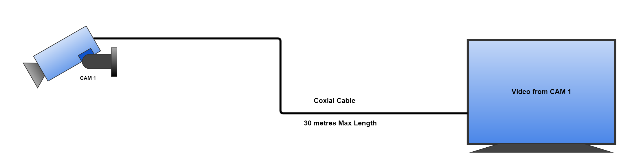
The Camera will capture live video and send it down the cable where the TV will pick it up and render the video on to the screen. Its that Simple!
There are limitations to this system as the cable should not exceed 30 metres as the video signal will start to degrade which will affect the video quality displayed on the TV. Also, it is not flexible enough to allow multiple cameras to be added in the future.
Adding Multiple Cameras To The System
Once you have this setup you may want to add more cameras to the system. Unfortunately, it is not as simple as plugging in more cameras to the TV. For starters, most TV’s don’t have enough connections to allow this, and secondly, two cameras cannot be connected to the same connection as both video signals will interfere with each other. To add more Cameras you need either a Video Processor or a DVR.
Multiple Cameras With A Video Processor
A Video Processor is a very low cost way of connecting up multiple cameras into a CCTV system. It’s a device that has a number of input channels and a single output channel. It takes the the video input channels and combines them into together a single output channel that can be connected and displayed on a TV or Monitor. This device is very easy to use and doesn’t need any configuration to get started. Just plug in each camera directly into one of the input channels and connect it up to a TV up to the output channel.
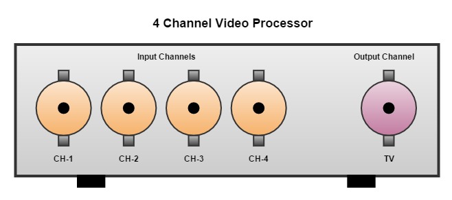
The number of input channels are usually 4, 8, 16, etc. Each of the input channels can be connected to a single CCTV Camera. This means that if the Video Processor has 8 input channels, a maximum of 8 CCTV Cameras can connected to the system. So if you are thinking of buying a Video Processor make sure you think about the number of Cameras you need right now and the number of Cameras you might need in the future. It is always better to have a Video Processor with number of spare channels should they be needed later.
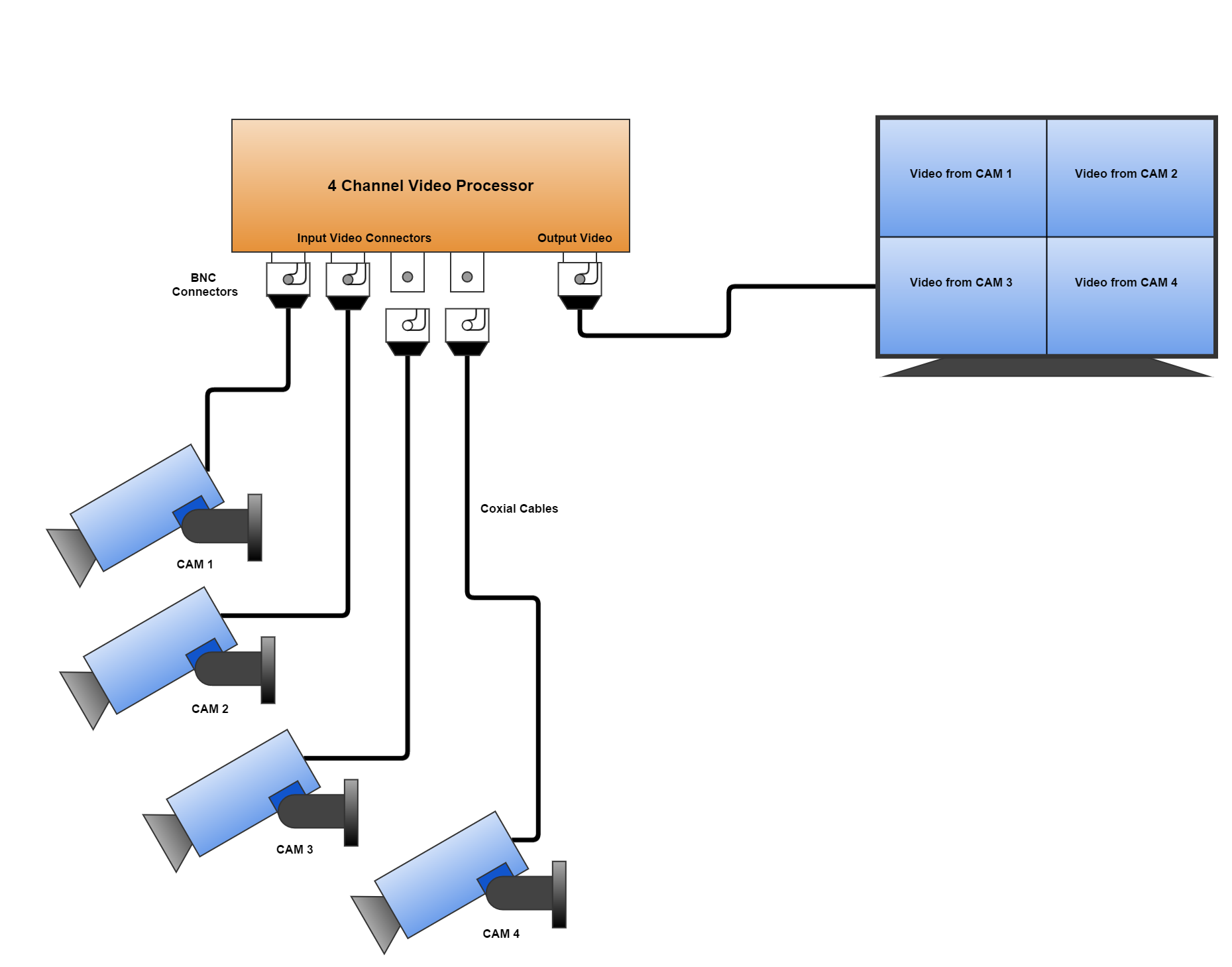
The device will take all the input channels and combine them all together into a video grid and sent it to out the single output channel. As shown in the diagram above all four video inputs from the cameras are visible on the TV screen at one time.
Video Processors have the capability of viewing all the channels at one time, in a grid, or allow the user to select an individual input channel one at a time in full screen. For example; you could select to only see video for Camera 3 on the TV. There is also an auto feature that will loop through each input channel one at a time. This can be useful as you will get to see a full screen video from each camera. The time that each channel is displayed in the loop can also be configured by the user (for example; 5, 10 15 seconds). Most of these devices also come with a remote control that is useful for changing these settings and flicking between video input channels manually.
Multiple Cameras With A DVR
A Digital Video Recorder (DVR) main features are that it can connect up multiple cameras together, like the Video Processor, but it can also record the video from the cameras. A DVR has an internal Hard Drive that it uses to store live video from the cameras. This means that you can look back on passed video from the cameras at a later point. This is a fantastic feature as it makes the Calving Camera work as a security camera and could be useful in the event of a theft on your farm. As with the Video Processor, DVR’s also come with different numbers of input channels (4, 8, 16…) so if you are purchasing one of them take note of the number of ports.
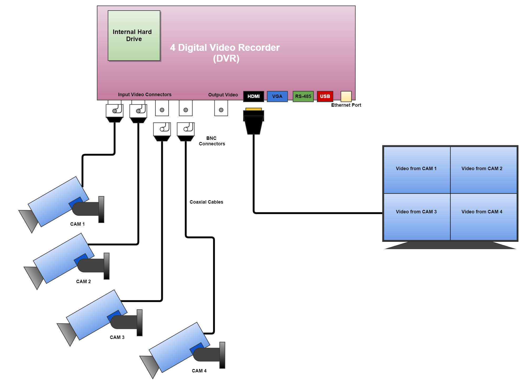
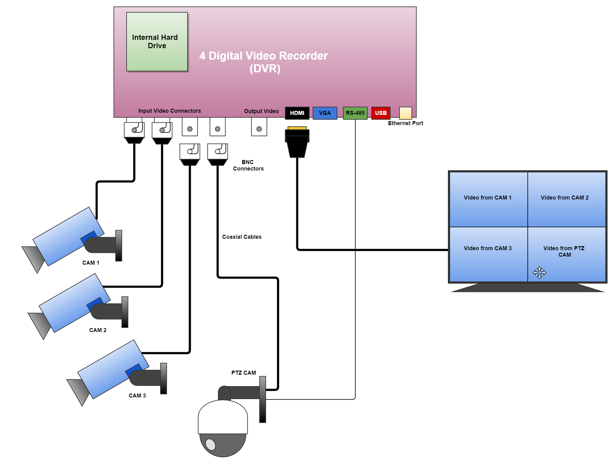
DVR video output connectors
A DVR usually comes with a lot more connectors than an standard Video Processor that can be used to connect it up to different devices and with different cables. It will have a female BNC connector, same as the Video Processor, which can be used to connect the DVR to a TV, or you can use a HDMI cable, or the VGA cable.
Connecting a PTZ Camera to a DVR
Most DVRs come with a RS-485 connector. This connector can be used to control the Pan/Tilt & Zoom (PTZ) of an Analogue PTZ Camera. An Analogue PTZ Camera will have a coaxial cable, just like the the bullet cameras for the video, but it also has a two core wire that needs to be connected into the RS-485 connector on the DVR. This is for controlling the PTZ of the Camera. So if you want to add a PTZ camera, or thinking of adding one in the future, it’s a good idea to check that the DVR has this RS-485 connector.
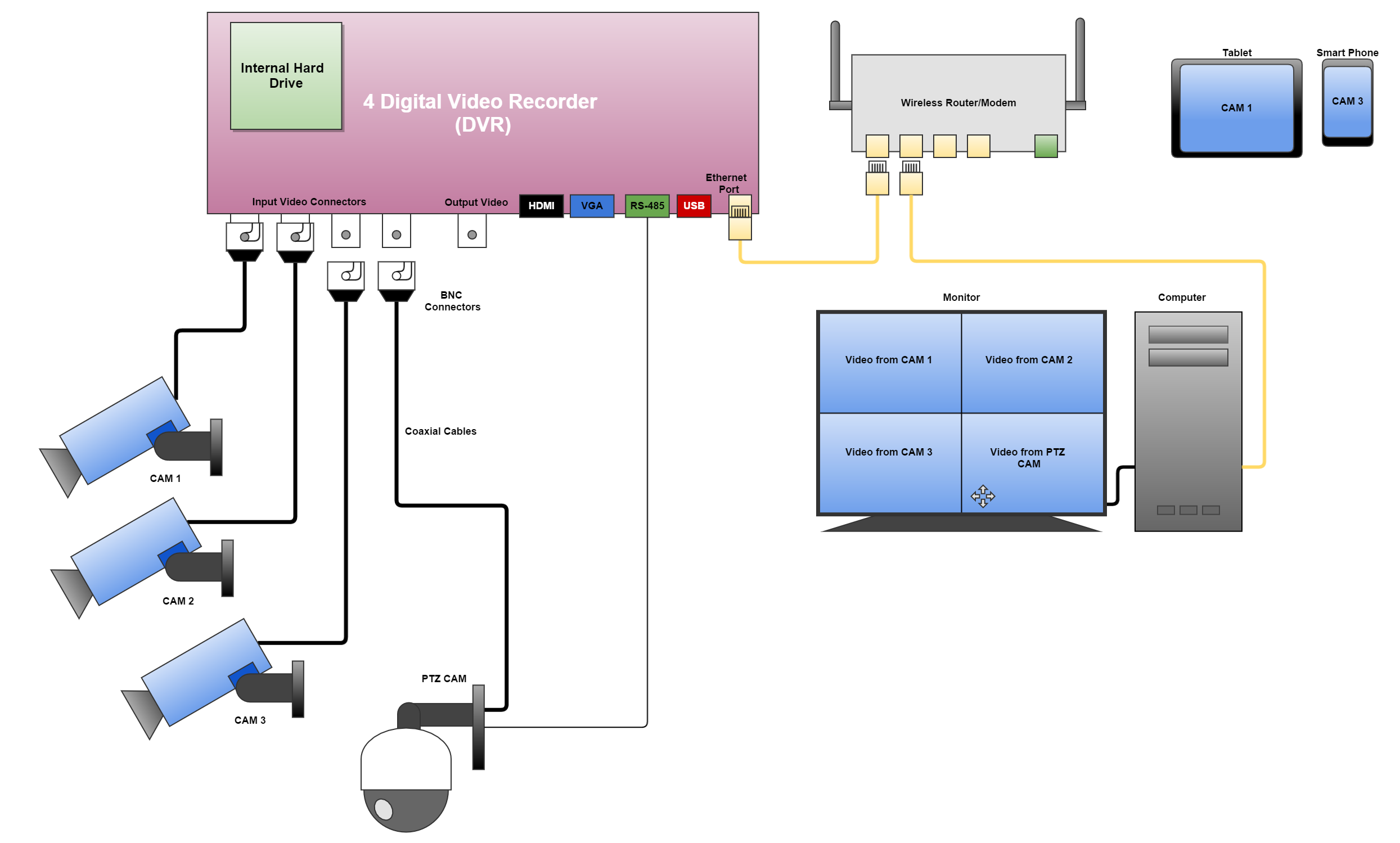
DVR Ethernet Connection
Most DVR’s also have an Ethernet port which means that you can connect the systems up to an Ethernet Network. This can allow you to login to the DVR from a PC, Laptop, or Smartphone and view the video from the cameras. This can be a very nice feature to have as it mean that the system can now be connected up to the Internet for remote viewing.
DVRs are more expensive than Video Processors but you do get a lot more functionality with them. The downside to them are they are a little more complex to configure and manage than a simple Video Processor.
In the next article we will talk about expanding the system to include wireless transmitters. This will increase the range of the above sytems so that the calving camera can be located behond the recommend length of a wired cables. This article will be up very soon.